With the barrage of dating shows coming at us from every streaming and TV angle, I couldn’t help but think about couples, which led me to think about how cool the concept of code “coupling” really is, especially in Avionics. Indeed, two things working together to ultimately make something greater than the sum of their parts is the most important idea in all-things aerospace and aviation. Rather, aviators and aerospace engineers of all specialties and functions know that strong relationships between entities are vital to every task, plan, and project in this field. So, the coupling we’re talking about today isn’t just some “summer fling” recorded for Netflix. Let’s talk about the importance of data coupling and control coupling in software projects.
Data coupling and control coupling are useful applications within DO-178C projects that, when done right, help achieve project objectives faster and with better outcomes. Unfortunately, how to precisely apply and ultimately satisfy the Data Coupling and Control Coupling objectives of DO-178 isn’t always understood. The limited information provided by DO-178B about these concepts didn’t accurately address Data and Control Coupling application, and the changes made in DO-178C’s updates often confused the issue for developers. So, this article covers the “real deal” of Data Coupling and Control coupling—what they are, how to apply them to your project, and why they’re important.
First, a quick background on both of these (no doubt, “cute”) couples.
Here are there definitions as stated in 178C:
Data Coupling (DC): The dependence of a software component on data, not exclusively under the control of that component.
Control Coupling (CC): The manner or degree by which one software component influences the execution of another software component.
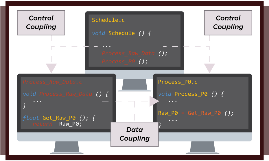
What exactly do these definitions mean, or rather, how do we apply them in “live” situations? In terms of avionics software development, it’s easiest to explain this using code examples. See this image:
 Data Coupling and Control Coupling Flow Chart
That example shows three components and the flow of control and data between them. The Scheduler invokes two components Process_Raw_Data and Calculate_P0. The data Raw_P0 is passed between the two components.
This simplified example illustrates the Control Coupling between the Schedule, Process_Raw_Data, and Process_P0 and the Data coupling between Process_Raw_Data and Process_P0.
Steps in Data Coupling and Control Coupling Sequencing
In order to verify that the design does not contain DC and CC related errors, and that the code correctly implements the design, it is necessary to perform Requirements Based Testing (RBT) activities on an Integrated software build. Following the example above the following should be covered by Requirements Based Tests:
1. Scheduler calls Process_Raw_Data
2. Schedule call Process_P0
3. Raw_P0 is passed from Process_Raw_Data to Process_P0
Note: these tests can be performed separately.
The key thing to remember of the DO-178 objectives is to cause the developer to consider data and control coupling as part of the design and implementation, and then ensure that all defined Data Flows and Control Flows are exercised during Requirements Based testing. Simply put, when your coupling code runs correctly during testing, you’ll save yourself from running over on time and headaches.
How to apply Data Coupling and Control Coupling
When applying DCCC as part of the software design process, always identify Data Flow and Control Flow between components, and be sure to record these flow steps in the Software Architecture As alluded, it’s necessary to define the Data and Control Flow in order to be able to identify the coupling in the design so that it can be reviewed and accepted.
It should be noted that during the design process choices will be made about what mechanisms will be used to enable the flow of data and control within the software system. These choices will also be dependent on what the design philosophy is, what facilities the implementation language supports and what the application is actually doing. The Architecture simply documents the designed Data Flow and Control Flow so that it can guide the implementation. Note also that the definition of Data Flow and Control Flow are considered part of the Architecture, not the Low-Level Requirements.
To summarize, test Coverage of software structure (data coupling and control coupling) has been achieved when you have:
1. Verified, by Requirements Based Tests, on an Integrated Build that any Shared Data Item between components has been Exercised.
2. Verified, by Requirements Based Tests, on an Integrated Build that Interactions between components have been Exercised.
Ultimately, there are number of strategies and activities that can provide the evidence that the Data Coupling and Control Coupling DO-178C objective has been met. For more information on Data Coupling and Control Coupling and how to best apply it to DO-178C projects, check out our white paper with more code examples and details on how to use these awesome applications.
Happy coupling!


